


📍 Low Level Design Series: Introduction, UML Diagrams
👉 Beginner Friendly approach to Low-level design bits like Behavioural UML Diagrams


Table of contents
🙂 Many beginner developers focus on the code instead of the design, which is okay. But at a later point in time design plays a lot more importance as compared to code implementation.
"A Poor Designed and Well Coded Application is bound to have bugs and scalability issues". 😨

🔥 Well This series is exactly what any developer needs to build good Design Skills. We'll complete the LLD (Low-Level Design) Series along with some projects and then we'll move on to the HLD (High-Level Design) Series. So, Follow for more.
📍 LLD, UML: What exactly it is?
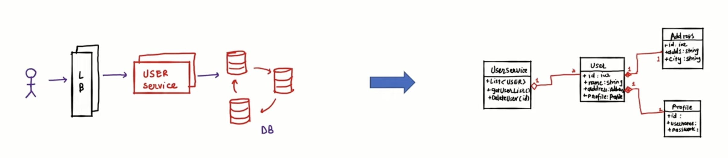
LLD means low-level design or in general Class level design. In the following diagram, you can see HLD on the left side which doesn't tell us any implementation while on the right we have a class diagram which is a category of Structural UML Diagram.
👉 UML is nothing but a graphical way to represent some relations/classes and is called Unified modeling language. We use UML diagrams that make our code implementation easier. Also, We do follow object-oriented principles or SOLID principles while writing the code from the UML Diagrams.
🎯 Benefits of using UML Diagrams:-
Develop a quick understanding of a software
Breaks complex systems into discrete pieces
Graphical representation makes the communication of the design easier
Easy to understand and can be handed to another team easily
🎯 Types of UML Diagrams are:-
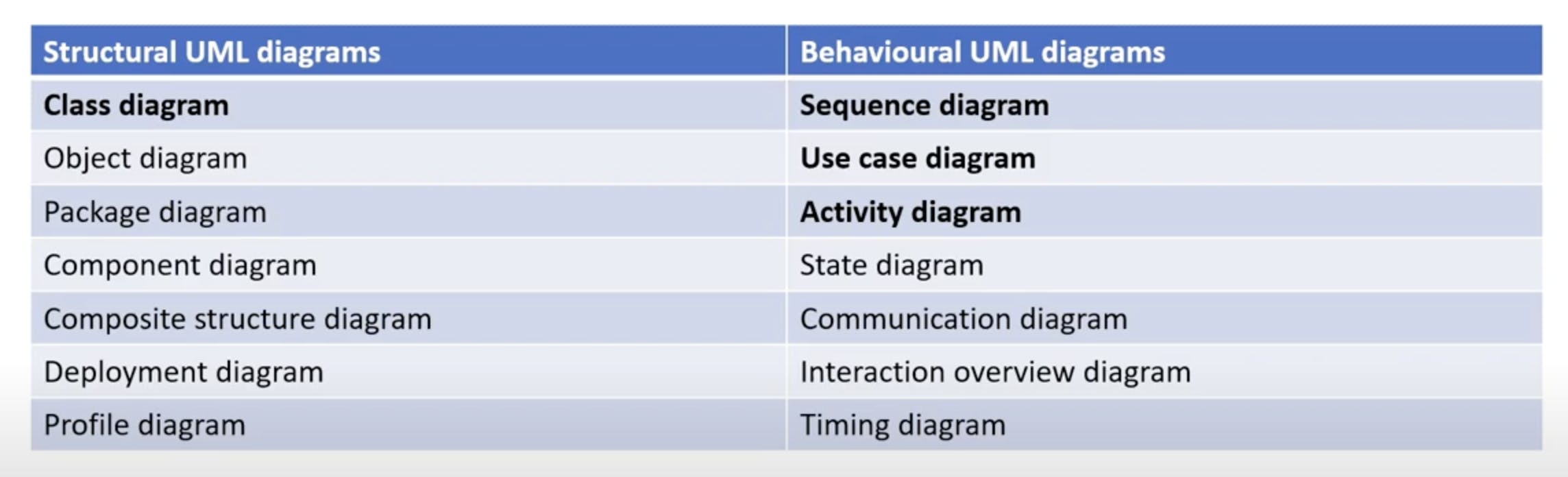
🧘 We'll mainly focus on the Class diagram, Sequence diagram, Use Case Diagram and Activity Diagram.
📍 UML Diagrams
- Use Case Diagram
It will give us the information about:-
High level functional behaviour
What system does from the user point of view
What system do and what it does not
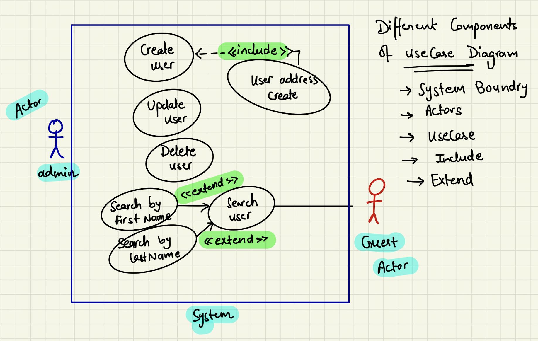
👉 Here, the system is based on managing the user where "Include" means the functionality is included in the other functionality and the "extend" means the sub use cases are extending the generic defined use case.
- Activity Diagram
It gives us the information about the:-
Events happen when an actor interacts with the system functionality
State diagram and the possiblities

- Sequence Diagram
It has two dimensions:- Vertical and Horizontal. Vertical is a sequence of messages that can be represented in chronological order and Horizontal is the one having Object instances to which messages are sent.
Let's see via graphical representation for more clarity:-
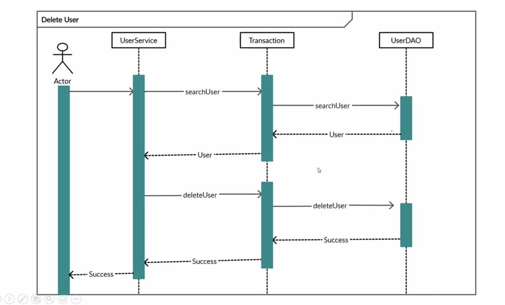
🤜 Here, you can see that DeleteUser is the transition from one state to another state. It gives us the detail at the object level.
🔥 Note:- Our main UML is Class Level Diagram. We generally do not use Behavioural UML Diagrams like Use case, Activity and Sequence Diagrams.
🙂 In our next blog of the Series, We'll see Object oriented Design Principles like SOLID and then we'll jump to the Class level Diagram and Projects. Follow and Stay Tuned.